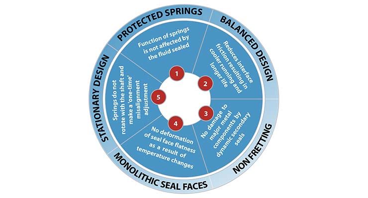
 Mechanical seal designs come in a wide variety. These designs differ in the way they are driven, the choice of secondary seals, and the location of the springs. Mechanical seals have all been designed to meet certain criteria in terms of application, cost, fit, ease of installation, and capability to seal. There are, however, a few basic characteristics that are common to any good mechanical seal design.
Protected Springs
Many early mechanical seal designs placed the spring inside the process fluid. Most products (process fluids) that are sealed are not very clean. When the spring mechanism of the mechanical seal is immersed in this unclean fluid, dirt collects between the springs. This situation eventually impacts the spring’s ability to respond to movements and vibrations, and the ability to keep the seal faces closed. Over time, clogging of the springs will cause premature seal failure.
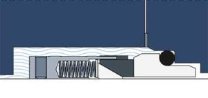
Unprotected Springs
The ideal design offers springs on the atmospheric side of the mechanical seals. The springs will be protected from the process fluid and their ability to work will not be impeded.
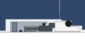
Protected Springs
Balanced Design
The pressure from both the seal springs (Ps) and the hydraulic pressure of the liquid in the pump (Pp) provide a compression force that keeps the seal faces closed. Balanced seals reduce the seal ring area (Ah) on which the hydraulic pressure of the liquid in the pump (Pp) acts.
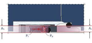
Unbalanced Design
By reducing the area, the net closing force is reduced. This allows for better lubrication that results in lower heat generation, face wear, and power consumption. Balanced seals typically have higher pressure ratings than unbalanced seals.
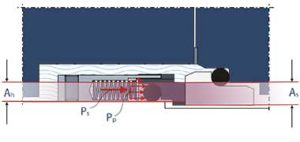
Balanced Design
The balance ratio (B) of a mechanical seal is given by the ratio of the hydraulically loaded area (Ah) and the sliding surface area (As):
- Balanced mechanical seals have a balance ratio B<1
- Unbalanced mechanical seals a balance ratio B>1
- The balance ratio is often between 0.6 and 0.8
- Lower balance ratios result in a thicker lubricating films and higher leak rates
- The choice of the balance ratio is a compromise between lower heat generation, leak rates, and stability of the sealing gap
Monolithic Seal Faces
Mechanical seals can be designed with inserted seal faces or with monolithic seal faces. In both cases, the sacrificial seal face is often made from carbon/graphite. This material offers good running properties but is relatively weaker from a mechanical standpoint than other options. Inserted face designs use a metal rotary holder to transmit the shaft torque to the seal face.
The disadvantage of this inserted face design is that the face and holder material have different coefficients of thermal expansion. This changes the net interference force between both parts when they are exposed to heat from the process fluid or face friction. The seal face deforms, which results in leakage and accelerated wear.
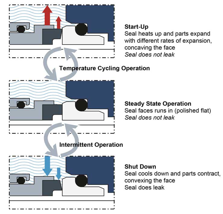
More modern seals are equipped with monolithic seal faces that are made out of only the seal face material itself. The torque transmission is applied directly to the seal face. This is possible if the geometry of the seal face is designed in a particular shape to give it the strength to handle the torque through its geometric design. These monolithic seal face designs have been made possible through the use of Finite Element Analysis (computer modeling).
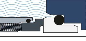
Monolithic Seal Faces
Monolithic seal faces provide a more stable fluid film between the faces, and they do not deform in operation compared to inserted faces (or to a much lesser degree). Therefore, they are more commonly used nowadays when reliability and low emissions are vital.
Non-Fretting Design
All mechanical seal designs have at least one secondary seal that interacts with the dynamic movement of the flexible mounted face. This secondary seal moves with the springs to keep the seal faces closed and is defined as the dynamic secondary seal. During operation of a rotary design, springs will keep the seal faces closed. They adjust with each rotation for any misalignment from installation and parts tolerances. As the springs compensate, the dynamic secondary seal moves back and forth, twice per revolution. This rapid movement prevents the protective chrome oxide layer (the layer that protects the metal) from forming. Erosion of this unprotected area under the dynamic secondary seal will cause a groove to develop. Eventually this groove becomes so deep that O-Ring compression is lost and the seal leaks. In most cases, fretted shafts must be replaced to achieve an effective seal.
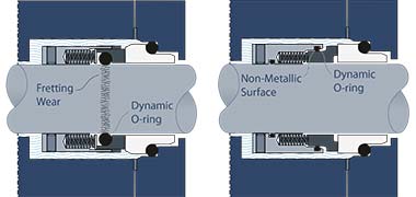
Fretting
Non-fretting seals are designed so that the dynamic secondary seal rides on a non-metallic surface, usually the sacrificial face.
Stationary Design
A rotary mechanical seal has the spring mechanism in the rotating section (A) of the mechanical seal.
With rotary mechanical seals, it is important that the stuffing box face is perpendicular to the shaft for the faces to stay closed. There will always be some resulting misalignment from installation and parts tolerances. The springs must adjust with each rotation to keep the seal faces closed. This adjustment becomes more difficult at higher speeds.
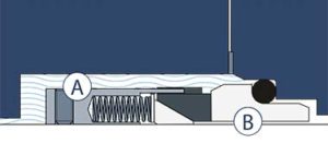
Rotary Design
In contrast, a stationary seal is a mechanical seal designed in such a way that the springs do not rotate with the pump shaft; they remain stationary. Because the springs do not rotate, they are unaffected by rotational speed. The springs do not need to correct or adjust with each rotation; they adjust for misalignment only once when installed.
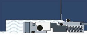
Stationary Design
Rotary seals are simple in design which makes them inexpensive. They are suitable for lower speeds only. Stationary seals are more complicated to design but are suitable for all speed ranges. Because of design complexity, stationary seals are more commonly configured as cartridge seals rather than component seals.
