 Does the condition of the equipment affect the life and performance of the mechanical seal? The answer is yes. Equipment conditions play a very important part in determining overall seal life and reliability.
Typically:
- Mechanical seals are installed onto a rotating shaft and designed to prevent visual leakage
- Two highly polished, spring-loaded “seal faces” come in contact with one another
- One of the sealing faces is stationary while the other sealing face is rotating along with the pump shaft
- Each of the two sealing faces are sealed to their mounts by a secondary seal—typically an O-Ring
Many factors come into play when a mechanical seal is installed onto a rotating shaft. A major consideration is the equipment condition, which includes the amount of shaft movement when rotating and/or condition of the stuffing box face. Mechanical seals are designed with assumptions regarding the amount of motion the devices can be expected to withstand and still provide no visible leakage during operation.
There are three basic rules to consider regarding mechanical seals and shaft movement:
RULE #1: The rotating shaft should not be bent and will rotate about its true axis
The desirable deviation from this assumption is no more than .001 inches/inch of shaft diameter or 0,001 mm/mm of shaft diameter (Figure 1).
If the shaft run-out exceeds these limits, then the lapped surfaces may have difficulty remaining together and, therefore, impact sealing.
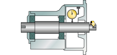
Figure 1
RULE #2: The rotating shaft supported by its bearing should not move axially (along its axis) more than 0.005 inches or 0,13 mm. (Figure 2)
If the shaft moves in excess of this amount, the force pushing the seal faces together may over-compress the polished seal faces which may cause excessive wear. If the shaft moves in the opposite direction, the shaft may under-compress the polished seal faces—allowing visible leakage.
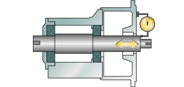
Figure 2
RULE #3: The mounting surface must be perpendicular to the rotating shaft
Run-out should not exceed 0.005 inches/inch of shaft diameter or 0,005 mm/mm of shaft diameter (Figure 3). If the mounting surface of the equipment is not perpendicular to the shaft, then seals which rotate their spring mechanism can suffer excessive wear on the drive pins or pads and fail.
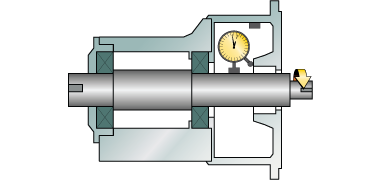
Figure 3
How Much Deviation is Acceptable?
A common question is: “How much in excess of these limits is allowable for proper function of the mechanical seal over the long-term?” Mechanical seals are remarkably resilient devices that can accept some shaft movement at high speeds. However, higher rotating shaft speed should be linked to minimal shaft movement to achieve the best mechanical seal life possible. If shaft speed exceeds 1800 RPM, then shaft run out should not exceed 0.002 inches or 0,05 mm for optimum mechanical seal life.
Best practices in industry incorporate an “as found” and “as left” data sheet which documents shaft run-out, shaft axial end-play and the seal chamber face run-out. Often standard procedures dictate if readings exceed set maximums, then shafts are refinished or replaced, and/or bearings are replaced. In some scenarios, seal installers will also take a “skim cut” off the face of the seal chamber to re-establish perpendicularity relative to the shaft which may have deteriorated due to corrosion from previous seal or packing leakage. This also provides a better static sealing surface for the next mechanical seal installation.
Assessing Seal Failure?
If you need help assessing your equipment relative to these standards, contact your local Sealing Specialist for help. If a seal fails, there is a more comprehensive troubleshooting checklist which we will cover in an upcoming blog, but checking adherence to the standards above is always the first place to start.
Set up a system to stay within these guidelines, and you will be making the most out of your seal investment and overall equipment reliability!