Our industrial pumps are wasting far more energy than we know – an estimated $10.2 billion/year! But by carefully watching and addressing pump efficiency, your facility can get control of these energy losses. In this post, we’ll look closer at what causes pump efficiency issues and specific steps for improving pump performance.
Pumps & Energy
In 2015, the US industrial sector consumed 800.7 million megawatt hours of electricity at a total cost of $56.4 billion. The pump portion of this is an estimated $10.2 billion of industrial expense.
Energy used by pumps tends to be an “invisible cost,” often buried in other expense lines. The reality is that improving the efficiency of a pump can have an enormous impact on increasing the return on investment (ROI) of each pump in your operation.
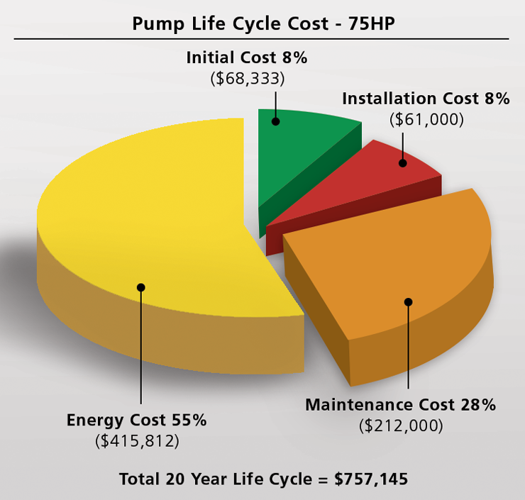
The lifetime energy costs to run a pump can dwarf the initial capital outlay for the pump itself (depending on the type of pump and how often it is running). These costs can be exponentially higher if a pump is operating far from its optimal efficiency point – often to the tune of tens of thousands of dollars across all the pumps at a single facility.
The Impact of Pump Efficiency
Plant managers are often surprised at the widespread nature of under-performing pumps. Several years ago, a Finnish research center* evaluated 1,690 pumps at 20 process plants. They found that the average pumping efficiency was below 40%, and that over 10% of the pumps were running below 10% efficiency.
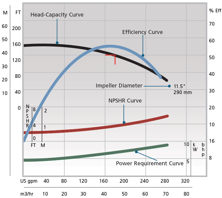
To check whether your pump is operating efficiently, measure the power it consumes and check it against the pump’s performance curve. The pump curve will specify how much power you should be using at the pumps generated flow and pressure. You can then identify the specific energy savings that can be achieved by addressing inefficiencies. Your local power company may also be willing to provide energy audits as a means to save energy and lower peak loads.
The major factors affecting pump efficiency include:
- Throttled valves
- Pump over-sizing
- Worn internals
Pump Performance Curve: The Standard to Measure Against
Pump manufacturers provide pump performance curves as part of their product documentation. The performance curve defines the pump’s performance level when brand new. The pump curve illustrates the flow and pressure (expressed as head) the pump will deliver when initially manufactured. The pump curve also indicates the energy required to generate a specific flow at a specific head (pressure). The energy requirements allow the motor size to be specified. This information is a valuable reference tool for maintenance staff over the life of the pump and can be useful during maintenance checks.
Checking the current pump performance versus the pump’s performance curve can:
- Avoid sudden pump failure/downtime
- Reduce energy consumption – often saving tens of thousands of dollars
- Prevent overtaxing the pump motor
- Extend the pump’s life expectancy
Troubleshooting
When the actual pump performance curve deviates significantly from the manufacturer’s documentation (pump standards will specify the maximum allowable deviation), it’s time to inspect the pump and surrounding system.
Here are some key items to review:
MOTOR-SHAFT ROTATION
Has the motor has been wired in the required direction as identified on the power end or casing? Users may find the flow from the pump is inadequate and blame the installation of a mechanical seal.
- If the motor is wired in the opposite direction of the required shaft rotation, the pump will only move fluid at a fraction of the flow and head for which it was designed.
- To check the correct pump shaft rotation, find the indicator on the bearing frame of the pump.
- Electricians can “bump the motor” to provide a split second of energy to check that the motor shaft rotation agrees with the rotation indicated on the pump bearing frame.
- Many mechanical seal manufacturers design bi-directional pumping rings in their seals to generate flow in either direction of shaft rotation. The seal can operate properly if the pump shaft rotates clockwise or counterclockwise. Be aware the pump will not perform at the level for which it was designed unless the motor is wired to enable the correct shaft rotation as indicated on the pump.
DEGRADED BEARINGS
Are the pump bearings degraded? Has the bearing lubricant become contaminated?
To maintain the reliability and the efficiency of the pump and to save energy, it is critical to protect pump-related bearings and monitor moisture in the lubricant. Industrial process pumps are often washed down, causing bearing lubricant to become contaminated and eventually damaging the bearing. Once water gets into the bearing lubricant, bearings can degrade very quickly.
Generally, motors used on centrifugal process pumps synchronize with the frequency of the electric current provided (typically 60 cycles in North America, and 50 cycles in the EU). However, the frequency can be controlled by a variable frequency drive (VFD), which then controls the rotating speed of the motor. Alternatively, a synchronous motor (also known as an alternating current motor) will seek as much current as it needs to maintain its speed.
If a shaft thrust or radial bearing is failing, it will exert a drag on the pump motor — requiring that motor to pull more current so it can rotate at design speed. In this situation, it will significantly drive up energy use/costs.
The important concept here is that while there are methods to get the pump to generate the specified flow and head (pressure), forcing this action with degraded bearings requires much more energy.
Ways to fix:
- Bearing protection technologies are available to protect bearing lubricants from contamination.
- Non-contacting labyrinth seals can be used to seal bearing housings to prevent this problem.
- Frequent checks
IMPELLERS & CASING CONDITIONS
Are the pump impeller(s) / casing in adequate condition?
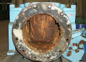
If you’ve checked the above items, and your pump performance deviates significantly from the manufacturer’s performance curve, you’ll want to look at the impact of erosion and corrosion. These forces can significantly change the shape of the impeller and/or the pump casing through wear or build-up and, ultimately, impact pump performance. Solids in the fluid flowing at high speed may change the shape of the casing and/or the impeller, therefore affecting the efficiency of the pump over time.
Wear rings
Some pumps are designed with enclosed impellers and wear rings. Wear rings are designed as a sacrificial component to inhibit re-circulation from the high pressure area of the impeller to the low pressure pump suction. If the mounting surfaces are corroded, the fluid will take the path of least resistance around the wear ring and flow into the pump suction, reducing performance. Pump manufacturers can mitigate these issues by using materials which are corrosion and erosion resistant. Slurry pump manufacturers often offer very hard casing and impeller material or rubber linings to prevent erosion.

 Protective coatings
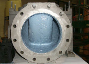
If the impeller or pump case has already been impacted and is affecting performance, refurbishing the worn areas and applying several layers of protective industrial coating can both restore efficiency and extend the life of the pump. In our experience, pumps protected with coatings can result in up to a 2-20% savings in specific energy use. Read more about this in an upcoming post.
CORRECT PUMP SIZE
Is the pump the correct size for the application?
Project engineers often deliberately use over-sized pumps for an application. They are anticipating that the pumped fluid will wear the casing and the impeller, and that eventually the worn pump will operate within an acceptable performance range. The issue with this approach is that until wear occurs, the pump discharge must be throttled by partially closing the discharge valve. This approach wastes considerable energy (and money).
Case Study: Over-sized Pump & Wasted Energy
The process requires 4000 GPM flow, but operations requested 4600 GPM for margin of safety. The junior Project Engineer calculated the head loss to be 39 feet @ 4600 GPM. The senior Engineer added 7 feet to the calculated head loss. The pump is sized for 4600 GPM and 46 feet of head @ 82% efficiency based on his experience. The process still only required 4000 GPM so the pump required throttling, so it was producing 50 feet of head @ 77% efficiency. At 4000 hours of operation per year with premium efficiency motor (95%), the energy wasted was over $6,000 per year – for this pump alone!
A Better Approach
The latest trend and a more economical choice is to purchase the correct sized pump and then protect the new pump casing and impeller from corrosion and erosion by applying a protective industrial coating (or purchase a pump that is already coated). This avoids the extra energy costs caused by throttling, increases flow efficiency, and extends the life cycle of the equipment.
If you have an existing over-sized pump, we recommend refurbishing and rebuilding with protective coatings, and then retrofitting the pump motor with a Variable Frequency Drive (VFD). The VFD allows you to use only the energy needed to get the flow needed at a particular point in time (without throttling the discharge valve) and, as a result, significantly lower energy use/costs.
Bear in mind that pumps which operate with partially closed discharge valves may be candidates for VFDs as a way of saving energy.
Summary
With a little pro-active, scheduled checking of a pump’s performance curve, you can take a big step in reducing issues and energy costs. If you are interested in a plant audit or would like more information, contact our Ask the Expert desk.
For more information:
Variable Speed Drives: A Way to Lower Life Cycle Costs (US Dept of Energy)
Chesterton Webinar: “The Energy Efficiency of Sealing Systems.”


